Getting Started with Multiple MMU Units
Happy Hare can combine multiple physical MMU units into one logical MMU. There is no fixed installer limit on the number of units, and the units do not have to be the same type. For example, one printer can use an ERCF alongside a Box Turtle or a ViViD. Each unit keeps its own hardware and movement configuration while the printer-wide settings are configured once.
This guide starts with a working single-unit installation and adds a second unit. The same process can be repeated for further units.
Configure first unit
Install and configure the first MMU in the normal way described by the Getting Started guide for that design:
./install.sh -i
Complete the configuration, save it, and validate that unit before adding another.
The initial unit is configured under the symbolic name unit0 by default.
Before adding another unit
Do not start with two untested configurations. Confirm the first unit's MCU, sensors and motors using Hardware Validation, then add the next unit. This makes wiring and configuration problems much easier to isolate.
Convert to multi-unit
From the Happy-Hare directory, rerun the interactive installer with -n:
./install.sh -i -n
The -n flag converts the existing configuration to multi-unit mode. It causes
menuconfig to run once for shared settings and then once for every unit in the
unit list.
Keep the first unit named unit0 during conversion
When converting an existing single-unit installation, the first entry must
remain unit0. That is the name associated with the configuration being
carried forward. Changing it at this point would create a new unit rather than
preserve the existing one.
Try the multi-unit installer safely first
Add the -t flag to rehearse the complete multi-unit installer workflow in
test mode:
./install.sh -i -n -t
Test mode uses a disposable configuration under /tmp/mmu_test and disables
service restarts, leaving the printer's real configuration untouched. It is an
ideal way to explore the shared and per-unit screens before repeating the
process for real without -t. See Running ./install.sh without touching
your printer
for details and the location of the generated test files.
Pass 1: shared configuration
The first menuconfig pass has a different color scheme and is labelled
Shared Config. It contains settings that apply to the complete printer rather
than to one physical MMU. Existing values are pulled from the first unit's saved
configuration; review them and update anything that should now apply to the whole
multi-unit setup.
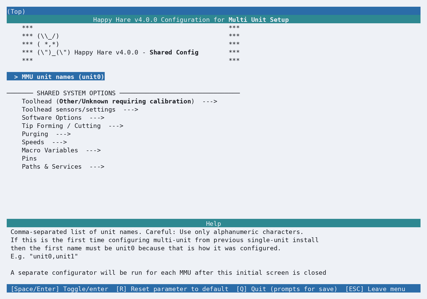
Printer-wide settings on this screen include the toolhead and its sensors, software options, tip forming and cutting, purging, speeds, macro variables, shared pins, and installation paths and services.
Select MMU unit names and add the new symbolic name. The editor presents one
unit per line; add unit1 below the existing unit0 entry.
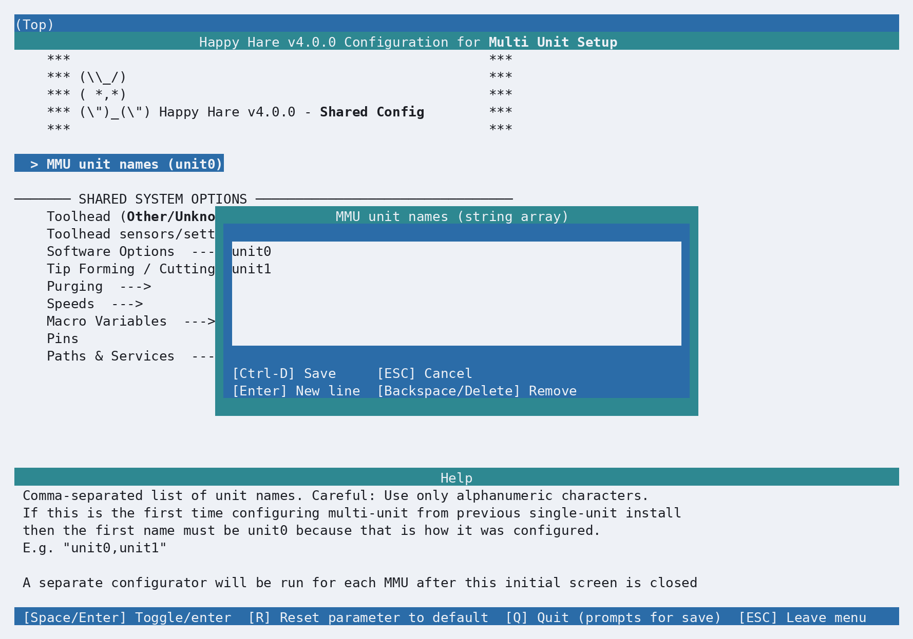
Press Ctrl-D to save the unit-name editor, then press Q and save the shared
configuration as usual. menuconfig now knows that two unit-specific passes are
required.
Symbolic names and display names
unit0 and unit1 are recommended symbolic names, but that naming pattern is not
mandatory for newly added units. The symbolic name associates Klipper objects and
generated configuration files with the physical unit, so keep it short, unique,
and alphanumeric. Avoid renaming an established unit unless you intend to
reconfigure it under a new identity.
Each unit also has a Display name setting. Use that for a friendlier label such
as ERCF Left or Box Turtle, including spaces. Mainsail, Fluidd and
KlipperScreen use the display name where appropriate without changing the
symbolic names in the configuration.
Pass 2: review existing unit0
The next menuconfig pass returns to the normal color scheme and is labelled
Unit: unit0. It contains only settings specific to the first physical unit.
Its existing configuration has been carried forward, but review the MMU type,
board and MCU connection, fitted features, pins, endstops and unit-specific
parameters before saving.
Press Q and save when the unit0 configuration is correct.
Pass 3: configure new unit1
The installer then opens a fresh unit-specific configuration labelled Unit: unit1.
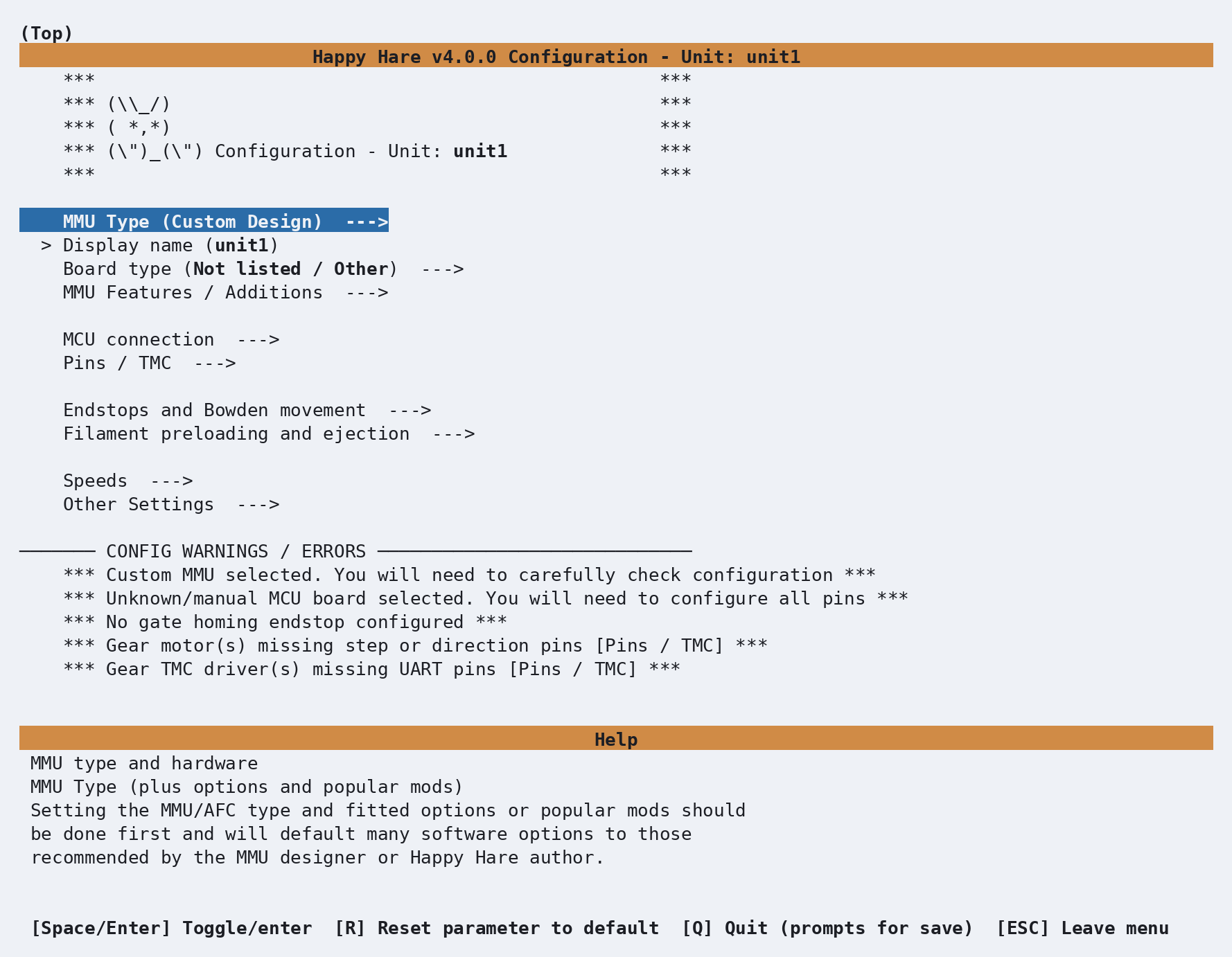
Configure this unit as thoroughly as a first installation:
- Select its MMU Type, version, and any design-specific project options.
- Set its user-facing Display name.
- Select its controller board and configure its MCU connection.
- Review its fitted features and additions.
- Configure and verify its pins, steppers, TMC drivers, sensors and endstops.
- Decide whether its encoder or sync-feedback buffer is independent or shared with an existing unit.
- Resolve every configuration warning, press Q, and save.
Removing a unit
From the Happy-Hare directory, rerun the interactive installer:
./install.sh -i
On the first, teal-colored Shared Config pass, open MMU unit names and remove the symbolic name of the unit you no longer want. Save the shared configuration, then complete the remaining unit-specific passes. When the installer finishes, it removes the generated configuration for the deleted unit.
Symbolic names cannot be renamed
The installer cannot currently rename an established unit's symbolic name.
The only workaround is to edit .mmu_config and every affected per-unit file,
such as .mmu_config_unit0 and .mmu_config_unit1, by hand so that all names
remain consistent. Use the unit's Display name instead when you only want
to change the name shown in Mainsail, Fluidd or KlipperScreen.
Where menuconfig choices are stored
.mmu_config contains the shared choices used by menuconfig, while files
such as .mmu_config_unit0 and .mmu_config_unit1 contain each unit's
choices. The installer also copies these files into
~/printer_data/config/mmu/. Before applying an installation, it backs up
the previous mmu directory to a timestamped location such as
~/printer_data/config/mmu.old-20260827-143000, so the earlier menuconfig
choices remain available if they are needed for recovery.
Sharing components
Multi-unit configurations can reuse hardware that is genuinely common to more than one filament path:
| Component | Multi-unit behavior |
|---|---|
| Toolhead | Shared by default and configured in the shared pass |
| Encoder | Can be owned by one unit and referenced by another if it sees filament from both units |
| Sync-feedback buffer | Can be owned by one unit and referenced by another when it sits in their common filament path |
Shared means physically shared
Do not select Shared with existing unit? merely to avoid configuring a second component. A shared encoder must measure filament from every unit that references it. A shared sync-feedback buffer must likewise be in their common filament path, typically after a combiner near the toolhead.
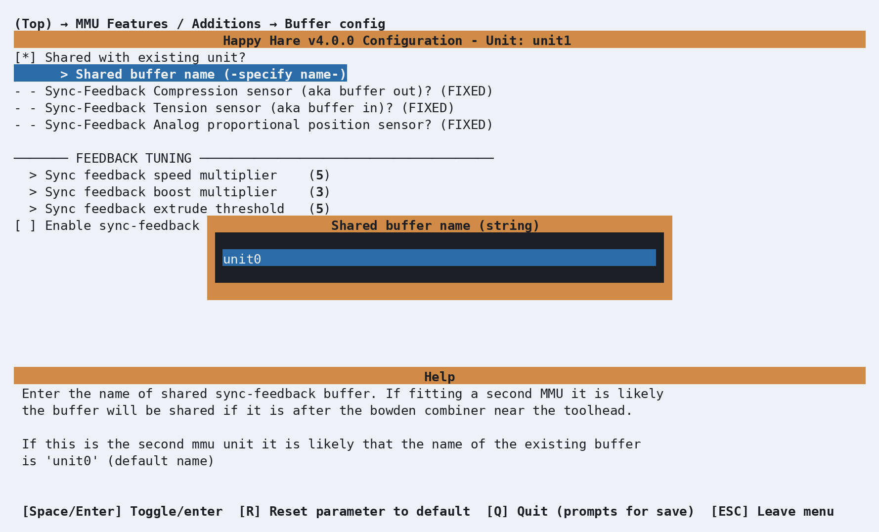
For example, to make unit1 use the sync-feedback buffer configured for unit0,
enable the buffer for unit1, open Buffer config, and select Shared with
existing unit?.
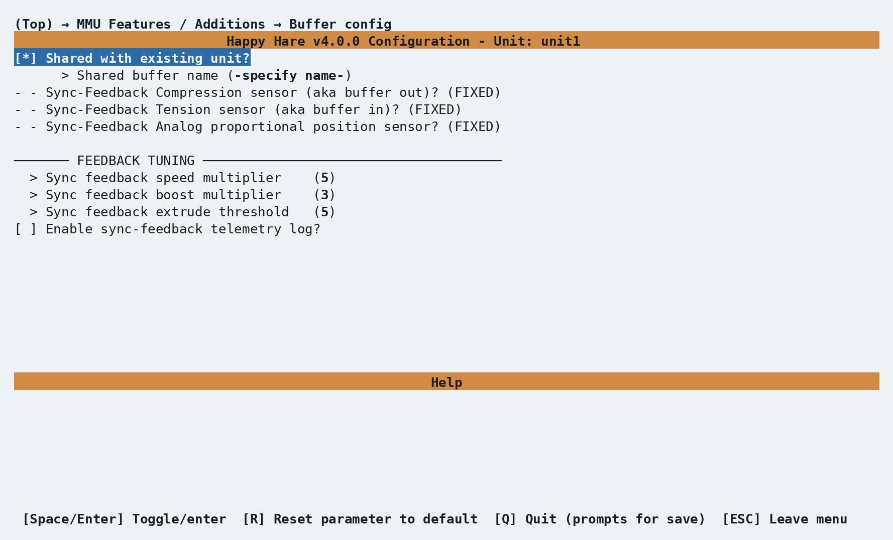
Set Shared buffer name to the symbolic name of the unit that owns the buffer,
in this example unit0.
See Encoder and Sync-Feedback Buffer for the hardware and tuning requirements of those components.
Bypass association
Happy Hare always makes a filament bypass available. Normally the UIs and console status render it as a separate lane, but one MMU unit can be associated with that bypass. This is particularly useful for a design such as ERCF with a selectable bypass gate, and lets the visualization draw the bypass as part of the correct unit.
Only one unit may have Associate bypass with this unit? enabled. Leave it off for every unit if the bypass should remain visually separate. See Filament Bypass for the available layouts.
Mainsail / Fluidd / KlipperScreen
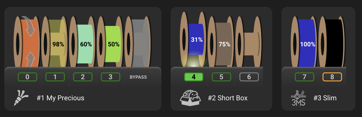
Mainsail, Fluidd and KlipperScreen display each physical MMU unit separately while presenting them as parts of the same logical MMU. Each unit keeps its own display name, design icon, gates and filament state. The bypass is shown either integrated into its associated unit or as a separate lane.
The Mainsail panel below shows three dissimilar units connected to the same printer: a four-gate ERCF with an integrated bypass, a three-gate Box Turtle, and a two-gate 3MS. The unit cards also make the continuous numbering visible: the ERCF uses gates 0-3, the Box Turtle uses gates 4-6, and the 3MS uses gates 7-8.
See Mainsail / Fluidd and KlipperScreen for their complete controls and status displays.
Gate and tool numbering across units
Gate numbers are global and sequential across the complete logical MMU; numbering does not restart at zero for each physical unit. Tool numbers are also global and sequential across the units.
For example, consider a four-gate unit0 followed by a six-gate unit1:
| Unit | Gates local to that unit | Global gate numbers | Default tools |
|---|---|---|---|
unit0 |
0-3 | 0-3 | T0-T3 |
unit1 |
0-5 | 4-9 | T4-T9 |
The default tool-to-gate map is one-to-one, so tool 6 maps to gate 6 in this example. The tool-to-gate map can change that association, but tool and gate identifiers remain global across the complete setup.
Most GATE= and TOOL= parameters therefore expect the global number. A command
uses a unit-local gate number only when it explicitly offers LGATE=. For example,
UNIT=unit1 LGATE=0 identifies the first physical gate on unit1, which is global
gate 4 in the table above.
Do not restart gate or tool numbering for unit1
On the example machine, GATE=0 and TOOL=0 refer to unit0. Use gate 4 or
tool 4 for the first gate or default tool on unit1, unless a command
explicitly requests LGATE=0 together with the unit.
Targeting units with MMU commands
Many MMU_* commands do not require a UNIT= parameter. Happy Hare can often
identify the correct physical unit from a global gate or tool number, or from the
currently selected gate. Other commands operate directly on one physical unit and
must be told which unit to use when more than one is configured.
When UNIT= is accepted, specify either its zero-based ordinal number or its
symbolic name. These two commands target the same unit:
MMU_HOME UNIT=1
MMU_HOME UNIT=unit1
Unit ordinals follow the order in MMU unit names: the first unit is 0, the
second is 1, and so on. Symbolic names are usually clearer in macros and saved
configuration because they show which hardware is being addressed.
Use these rules when deciding whether UNIT= is needed:
| Command context | Is UNIT= needed? |
|---|---|
A global GATE= or TOOL= uniquely identifies the unit |
Usually no; the owning unit is implied |
| The command acts on the currently selected gate and that gate is known | Usually no; the active unit is implied |
| The command controls one unit but has no gate or tool context | Yes on a multi-unit machine |
| Only one MMU unit is configured | No; the sole unit is selected automatically |
For example, these commands already contain enough global context to identify the unit:
MMU_SELECT GATE=4
MMU_CHANGE_TOOL TOOL=7
By contrast, unit-specific operations such as homing, motor control, encoder control, or selector calibration generally require an explicit unit on a multi-unit machine:
MMU_HOME UNIT=unit1
MMU_MOTORS_OFF UNIT=1
Some per-unit commands also accept UNIT=ALL to repeat the operation for every
configured unit:
MMU_HOME UNIT=ALL
UNIT=ALL is not universal. Check the command's entry in the
Command Reference, or run MMU_HELP CMD=<command>,
before using it.
UNIT can be mandatory
If a command cannot infer a unit and more than one unit is configured, it
reports that UNIT is required rather than guessing. Add UNIT=<ordinal> or
UNIT=<symbolic_name> and run the command again.
Generated configuration files
After the final unit is saved, the installer generates a separate hardware and parameter file for every symbolic unit name:
mmu_hardware_<unit_name>.cfg
mmu_parameters_<unit_name>.cfg
For the example above, the per-unit files are:
mmu_hardware_unit0.cfg
mmu_parameters_unit0.cfg
mmu_hardware_unit1.cfg
mmu_parameters_unit1.cfg
Shared configuration remains in the common Happy Hare files. This separation keeps each physical unit's hardware and movement settings readable while allowing Happy Hare to present all configured units as one logical MMU.
Reconfigure or add more units
Once the installation is multi-unit, rerun the normal interactive command:
./install.sh -i
The installer detects the saved multi-unit configuration automatically. It opens the shared configuration first and then opens one unit-specific pass for every name in MMU unit names.
To add a third or later unit, add another name in the shared pass and save. The
installer will review each existing unit in order and then open a fresh
configuration for the new unit. The -n flag is only needed when converting the
original single-unit installation.
After changing the setup, repeat Hardware Validation for every affected unit before printing.