Feature: Sync-Feedback Buffer
Concept
During a print, Happy Hare generally keeps the gear stepper synchronized to the extruder - moving together rather than the extruder doing all the pulling. This spreads the load and reduces under-extrusion caused by friction, but it depends on the gear stepper's calibrated rotation distance staying accurate. Even a well-calibrated system drifts a little over a long print: purging, high flow rates, drag along the filament path, and the inertia of a heavy spool can all cause small amounts of slippage, almost always in the gear stepper rather than the extruder. Left uncorrected, that drift accumulates into missed steps or under/over-extrusion.
A sync-feedback sensor - often called a "buffer" - sits in the bowden path between the MMU and the extruder and reports whether the filament there is under tension, under compression, or neutral. Happy Hare uses that signal to continuously correct the gear stepper's effective rotation distance, a process this documentation calls AutoTune. Four sensor styles are supported:
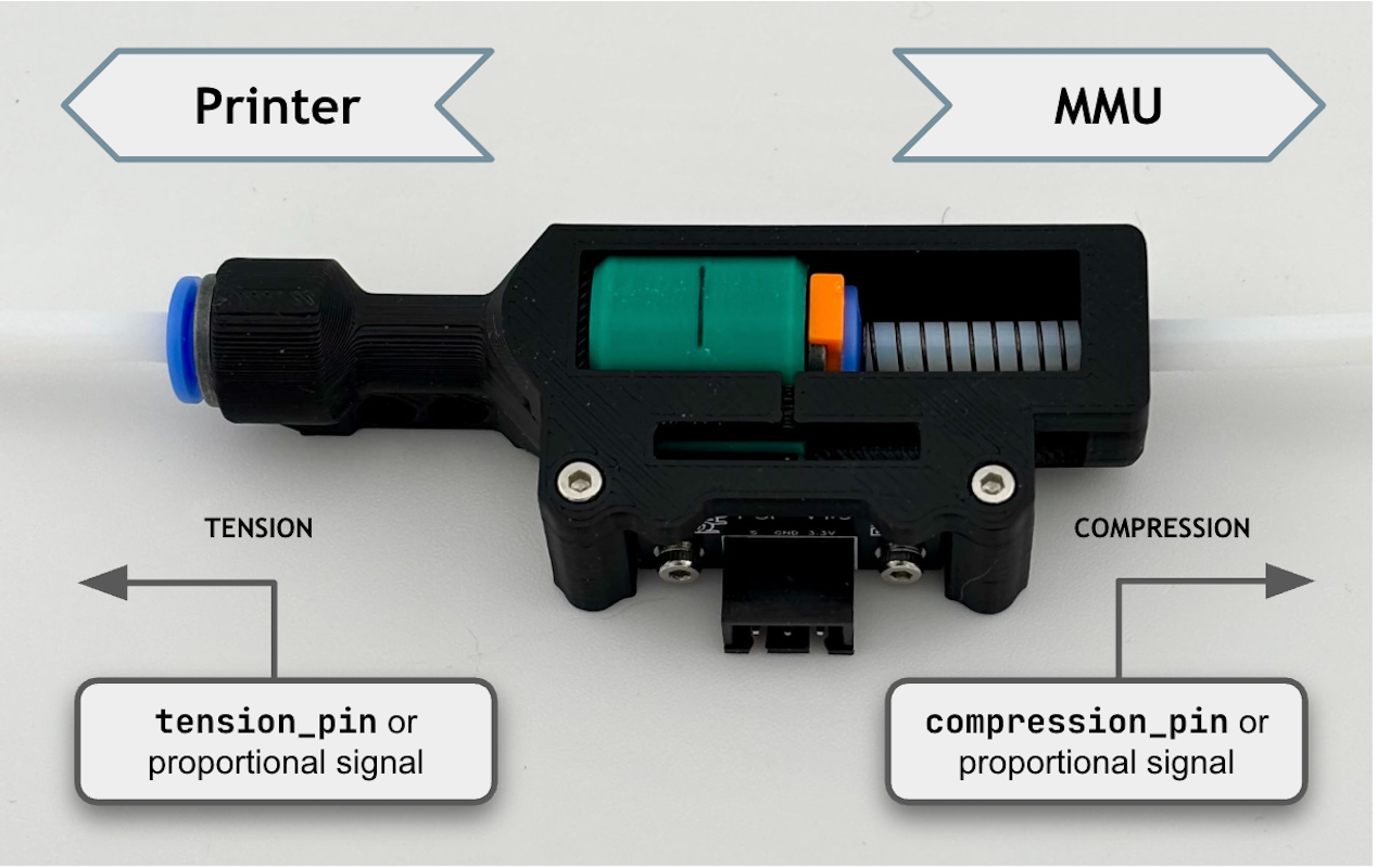
- Tension-only (TO) - a single switch that trips when the filament is under tension.
- Compression-only (CO) - a single switch that trips when the filament is under compression.
- Dual (D) - two switches, giving independent tension and compression signals with a neutral band between them.
- Proportional (P) - a single analog sensor reporting continuous position, including how far into tension or compression the buffer currently sits.
Which sensor style you have decides how AutoTune corrects things, and which of two algorithms it runs:
- Two-level (switch sensors - TO/CO/D): the gear speed is continuously
nudged a fixed % above or below the current rotation-distance estimate,
and which way the switches respond decides which direction is correct.
This means a switch sensor's gear speed is always oscillating in a
small, deliberate back-and-forth motion, even once AutoTune has converged -
that oscillation is how it keeps checking the estimate is still right, not a
fault.
sync_feedback_speed_multiplier/_boost_multiplier(see Parameter Setup below) control how wide that back-and-forth motion is. - EKF (Extended Kalman Filter - proportional sensors only): a statistical model correlates the sensor's continuous position reading with extruder motion to estimate rotation distance directly, with no need to hunt for a switch trip point at all - smoother, and generally more accurate once converged.
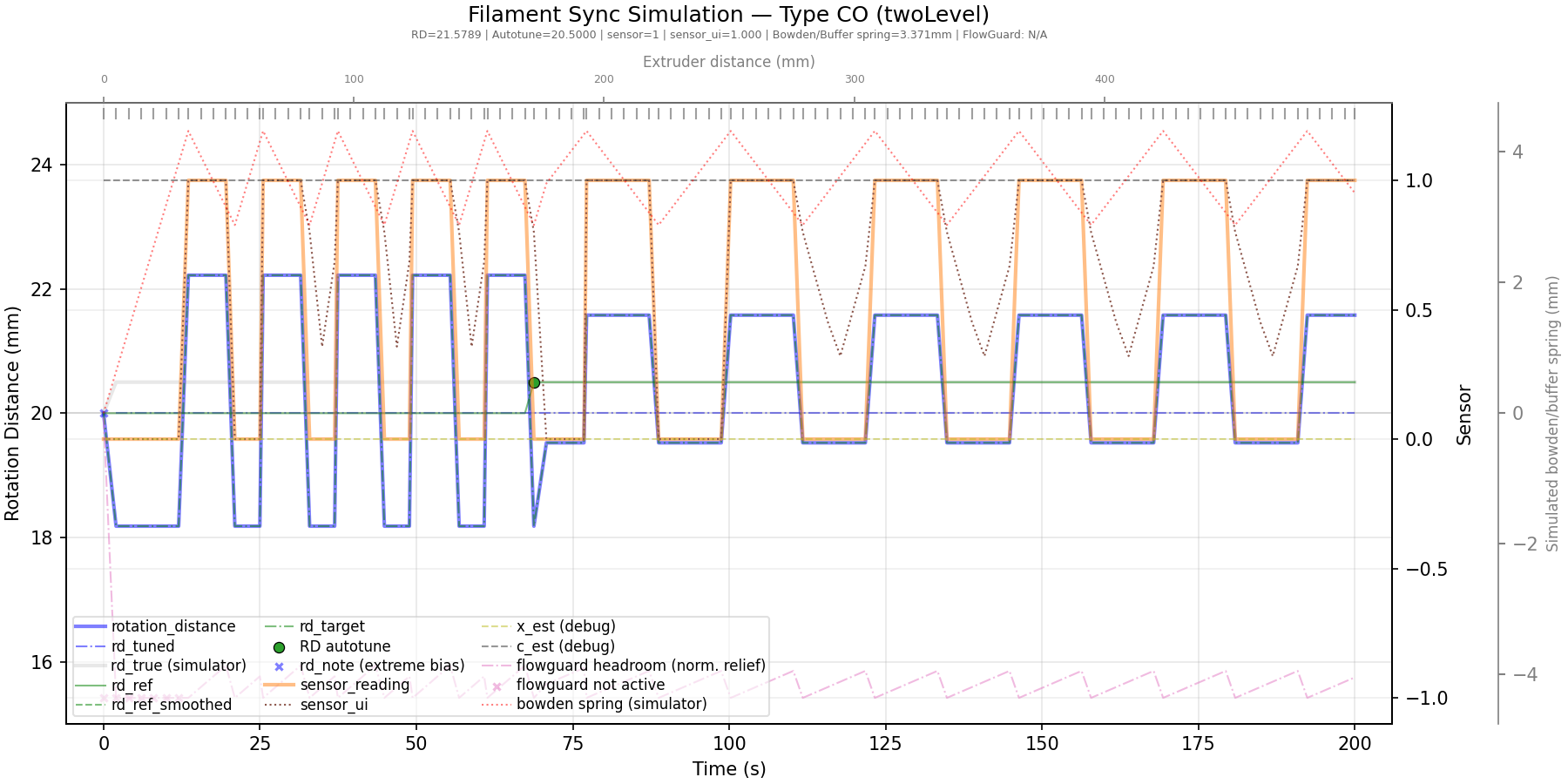
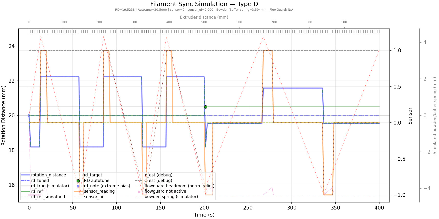
The gear's rotation distance (heavy blue line) starts off 20, but the
extruder's real value is 20.5 - visible as wide, fast oscillation at the
start that narrows as AutoTune homes in on the correct value. The
equivalent plot for a Type-D
sensor looks similar.
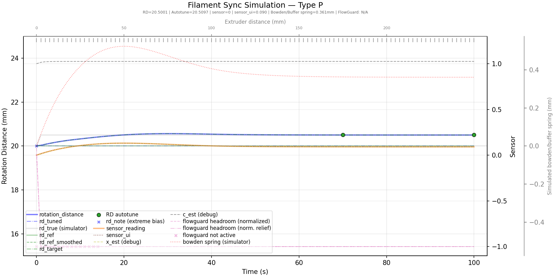
EKF mode converges the same way, just without the oscillation:
A sync-feedback sensor isn't only useful for AutoTune - a compression switch or a proportional sensor's threshold can also stand in as the extruder homing endstop, and either sensor type feeds FlowGuard's clog/tangle detection and its tangle-prevention current boost. Those two capabilities are covered on their own, since they're shared with other detection sources and have a fair amount of tuning of their own; this page covers the sensor itself, synchronizing gear to extruder, and AutoTune.
Hardware Setup
Examples below use the default unit name unit0. Substitute your configured
Klipper object name in unit-specific
sections, object references and pin prefixes.
Enable this under MMU Features / Additions, in a Buffer config submenu that only appears once Has sync-feedback buffer? is selected:
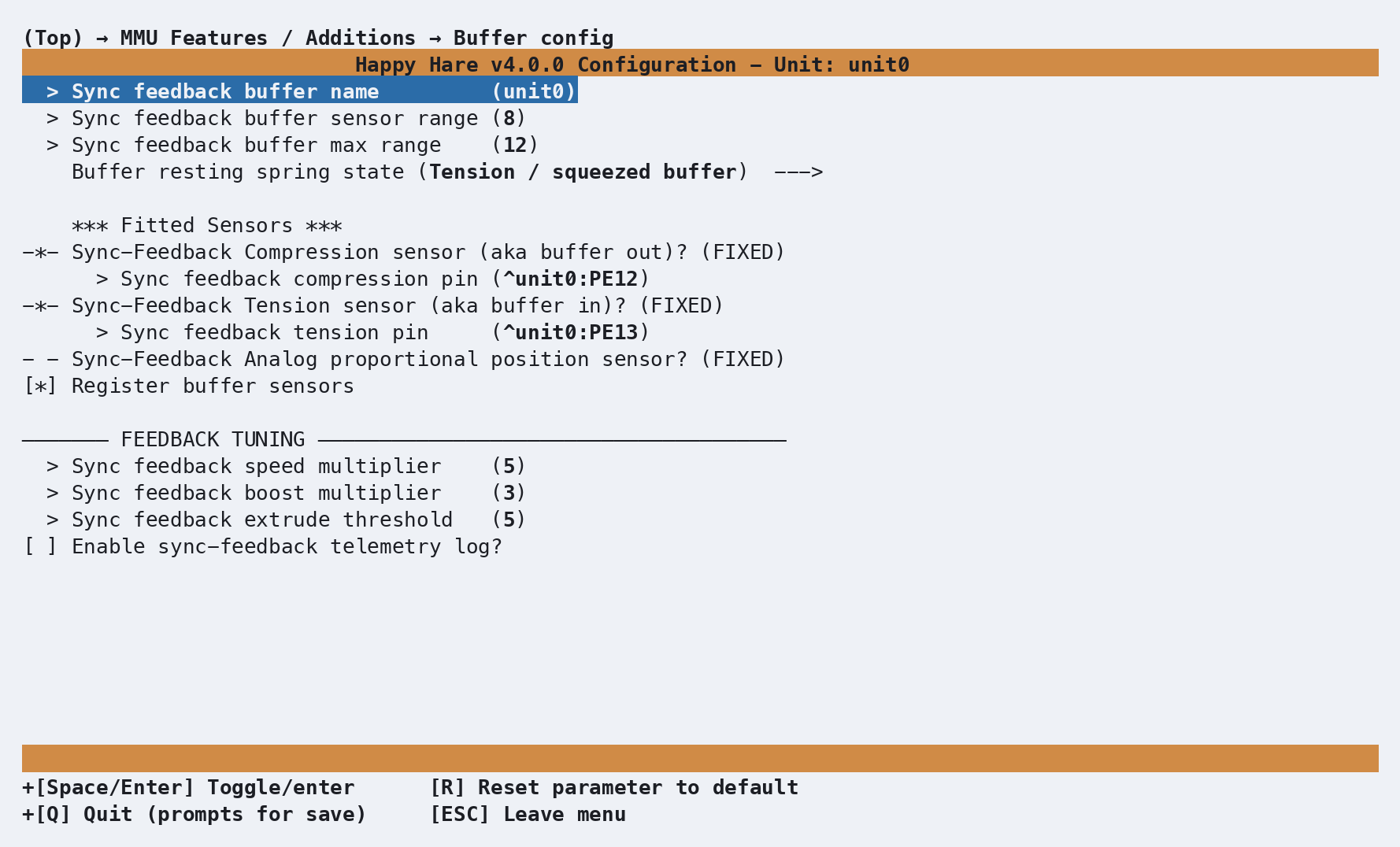
| Setting | Purpose |
|---|---|
Use shared buffer? |
Reference an existing buffer instead of defining one; available for single-unit and multi-unit installations |
Buffer name |
Klipper object name for an owned buffer; defaults to the unit name |
Shared buffer object name |
Name of the existing [mmu_buffer NAME] object when sharing |
Sync feedback buffer sensor range |
Travel between the compression and tension trip points (or between one switch and the buffer's end, for a single-switch design) |
Sync feedback buffer max range |
Total end-to-end travel the buffer mechanism allows |
Buffer resting spring state |
If the buffer is sprung and reliably rests in one position (tension, compression, or neutral) when unloaded, set it here to help filament-presence detection - n/a if it has no reliable rest position |
| Compression / tension switch pins | One or both, depending on your sensor - leave either blank if not fitted |
| Analog (proportional) pin and tuning values | Only for a type-P sensor - see Tuning below for calibrating these |
Register buffer sensors |
Whether the sensors also show up as filament switch sensors in Mainsail/Fluidd - purely a UI visibility toggle |
With sharing disabled, this produces one [mmu_buffer <buffer_name>] section
in mmu_hardware.cfg. The name defaults to the unit name but can be changed
independently. When sharing, no local buffer section or hardware pins are generated.
A matching configured owner supplies the sensor capabilities and resting spring
state. For a buffer defined in your own configuration, enter those capabilities
and spring state yourself.
An owned buffer using the default name looks like this:
[mmu_buffer unit0]
buffer_range            : 8              # Travel between compression/tension (or one switch and the end)
buffer_maxrange         : 12             # Absolute end-to-end travel
tension_pin              : ^unit0:PE13
compression_pin          : ^unit0:PE12
buffer_spring_state     : tension        # none|tension|neutral|compression

# Proportional sensor configuration - leave blank if using switches instead
#analog_pin              : pin
#analog_max_compression  : 1
#analog_max_tension      : 0
#analog_neutral_point    : 0.5
#analog_gamma            : 1
#analog_sensor_threshold : 0.9

register_buffer_sensors : 1
An empty switch pin simply means that half of the sensor isn't fitted - a
tension-only or compression-only design works fine with the other pin left
blank. Use MMU_SENSORS while manually
triggering the buffer by hand to confirm the orientation is wired the way
you expect - a squeezed buffer commonly means tension, an expanded one
compression, but it depends entirely on your specific mechanism.
The same Buffer config screen also has a Feedback Tuning section
below the sensors - that's the sync_feedback_* software tuning covered
under Parameter Setup next, not more hardware wiring.
Setting buffer_range/buffer_maxrange
Both are physical measurements of the buffer mechanism itself, used to
validate movement and optimize AutoTune - buffer_maxrange is the buffer's
total end-to-end travel, buffer_range is the distance specifically
between the trip points (or between one switch and the buffer's end, for a
single-switch design):
Possible buffer setups (dual-switch, compression-only, tension-only):

  <------maxrange------>       <------maxrange------>       <------maxrange------>
       <--range--->                  <----range----->       <----range----->
  |====================|       |====================|       |====================|
       ^          ^                  ^                                     ^
  compression   tension        compression-only                      tension-only
For a type-P (proportional) sensor, buffer_range is the distance over
which the raw ADC value actually changes - typically the same as
buffer_maxrange:
  <------maxrange------>
     <----range---->
  |====================|
  ^                    ^
compression        tension
Parameter Setup
Whether the gear stepper synchronizes to the extruder at all is a separate setting from the buffer itself, under Other Settings → MMU/Extruder sync:
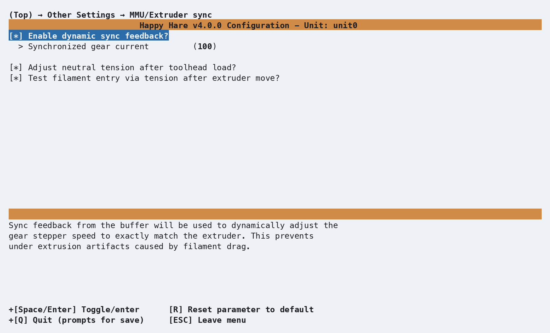
sync_to_extruder   : 1     # Gear motor synchronized to extruder during print
sync_gear_current  : 100   # % of gear_stepper current to use while synced
sync_form_tip      : 0     # Also synchronize during standalone tip forming
sync_purge         : 0     # Also synchronize during standalone purging

sync_feedback_enabled           : 1   # Use the buffer even though it's fitted (for temporarily disabling it)
sync_feedback_speed_multiplier  : 5   # % gear speed delta used to keep filament neutral (switch sensors)
sync_feedback_boost_multiplier  : 3   # % extra speed boost while first finding neutral (switch sensors)
sync_feedback_extrude_threshold : 5   # mm of extruder movement between AutoTune checks
sync_feedback_debug_log         : 0   # 1 = write a telemetry log for tuning (see Tuning)

toolhead_post_load_tension_adjust : 1  # Relax bowden tension to neutral right after loading (see below)
toolhead_entry_tension_test       : 1  # Check for neutral tension as filament passes the extruder entry (see below)
toolhead_post_load_tension_adjust is what actually drives the automatic
ADJUST_TENSION=1 call described under Commands below - on by
default, and only fires when synced to the extruder (or sync_purge) with a
tension/compression/proportional sensor active. toolhead_entry_tension_test
is a separate check, using a compression sensor differently: while synced
and loading without a toolhead sensor fitted, it checks for neutral tension
right as the filament passes the extruder entry, to catch a failed grip at
that specific transition early rather than discovering it further
downstream. It's ignored outright on any design with a toolhead sensor,
since that sensor already gives a more direct check.
Whether sync_to_extruder is a real choice or fixed on depends on your MMU
design: a design that can release its own grip on the filament (typically
one with a moving selector and a servo) can print without any
synchronization at all, so the setting shows as a genuine toggle. A
gear-per-gate design that always grips the filament has nothing to
choose - Happy Hare forces it on, and the toggle doesn't appear (the
screenshot above, from a gear-per-gate design, shows exactly that - the
sync toggle itself is missing, but the current and tension settings are
still present).
If you normally run the gear stepper near its maximum current,
sync_gear_current is worth lowering - it only applies while actually
synced during a print, and full power is restored automatically for
loading/unloading moves. Running a TMC-driven gear stepper at full current
for an entire long print is a common way to make it noticeably hot.
sync_feedback_speed_multiplier/sync_feedback_boost_multiplier only
matter for switch-based sensors (TO/CO/D) - a proportional sensor's
correction doesn't work by oscillating between two speeds, so these have no
effect with one fitted.
Tip
As with most mmu_parameters, every setting here can be changed live
with MMU_TEST_CONFIG <var>=<value> - no Klipper restart needed.
Commands
MMU_SYNC_FEEDBACK                    # Report sync-feedback controller status
MMU_SYNC_FEEDBACK ENABLE=0           # Temporarily stop using the buffer
MMU_SYNC_FEEDBACK RESET=1            # Reset the controller, restoring the last known-good rotation distance
MMU_SYNC_FEEDBACK ADJUST_TENSION=1   # Nudge the buffer back towards neutral right now
Full parameter reference: MMU_SYNC_FEEDBACK.
Happy Hare calls the equivalent of ADJUST_TENSION=1 automatically after a
filament load and again after purging, so this is mainly useful for
checking status or recovering manually. That automatic post-load call is
gated by toolhead_post_load_tension_adjust, covered together with the
related toolhead_entry_tension_test under Parameter
Setup above.
MMU_SYNC_GEAR_MOTOR          # Force sync on right now (SYNC defaults to 1)
MMU_SYNC_GEAR_MOTOR SYNC=0   # Force sync off and release the servo, on designs that have one
Full parameter reference: MMU_SYNC_GEAR_MOTOR.
Happy Hare manages this automatically during normal operation - reach for it
directly if you're operating the MMU by hand during a pause and want the
gear synced (or not) for what you're about to do. You can still move the
gear stepper on its own with
MMU_TEST_MOVE or
MMU_TEST_HOMING_MOVE
regardless of the current sync state.
Printer variables exposed
See sync feedback, FlowGuard and tangle prevention
in the printer variable reference - sync_feedback_state,
sync_feedback_enabled, sync_feedback_bias_raw/_modelled, and
sync_feedback_flow_rate (proportional sensors only).
Sync-feedback meter (Mainsail/Fluidd)
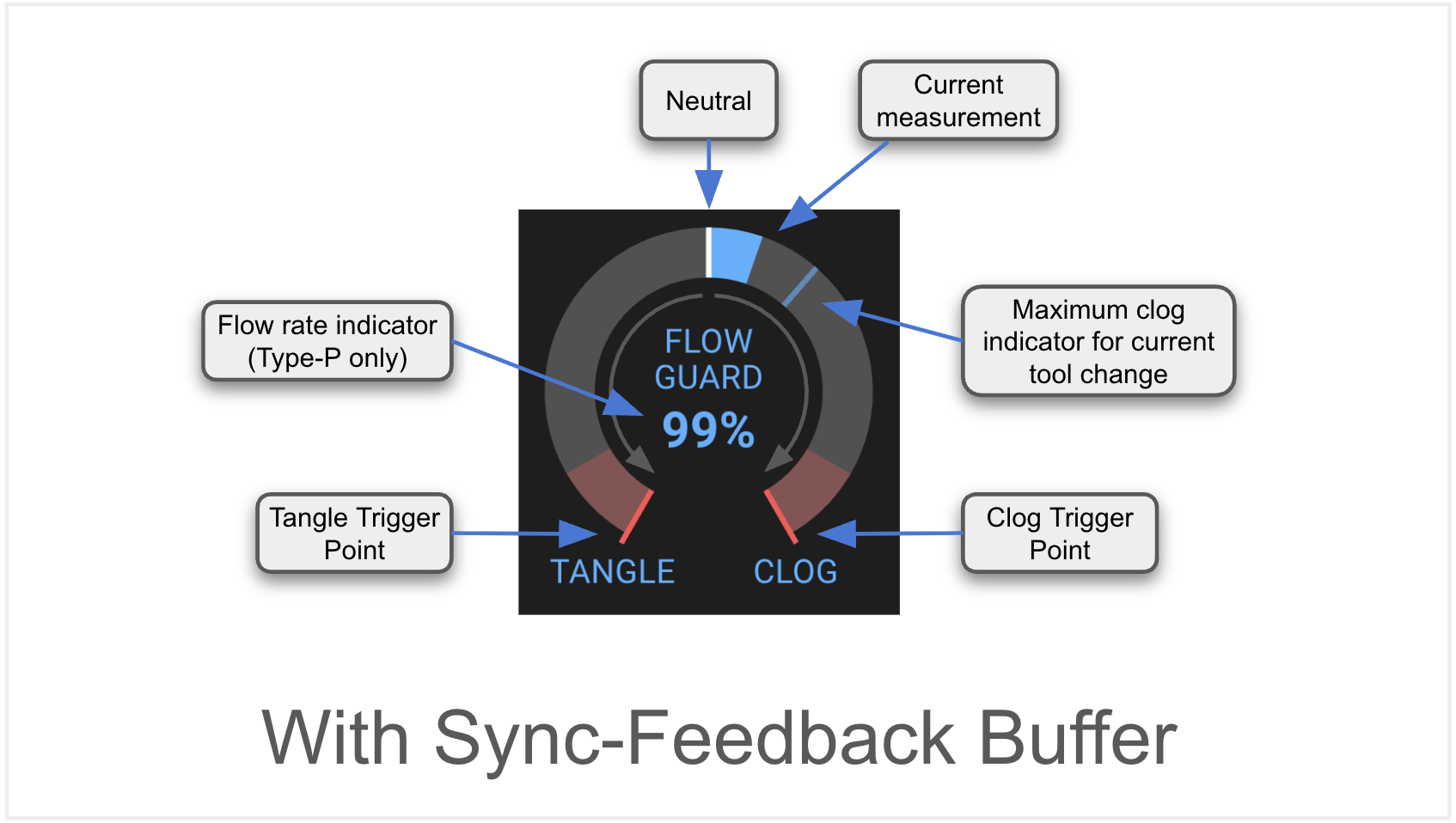
Extreme tension or compression is called out directly on the gate icon too, for a quick glance without opening the meter:
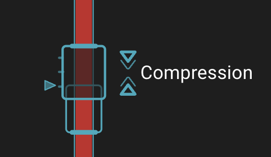 Switch sensor at an extreme (compression shown) |
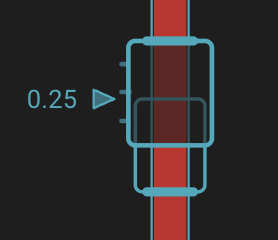 Proportional sensor's live position ( 0.25 here)
|
Tuning
- Switch sensors need no calibration beyond the physical
buffer_range/buffer_maxrangemeasurements in Hardware Setup - AutoTune starts oscillating and correcting as soon as the sensor is wired correctly. - Proportional sensors need a one-time calibration pass - see below.
- Enabling
autotune_rotation_distanceinmmu_parameters.cfgpersists AutoTune's live estimate as the calibrated rotation distance, so it's remembered across restarts instead of being re-learned from scratch every time - worth turning on alongside this feature. - If AutoTune oscillates or triggers false clogs/tangles, the usual
culprit is "play" in the filament path - a large-ID bowden tube or a long
run lets filament coil up inside it, which looks like more movement than
the sensor should be seeing.
sync_feedback_debug_log: 1writes a per-gate telemetry file for closer analysis - see Feature: FlowGuard: Tuning with telemetry for how to read one.
Calibrating a proportional sensor
With analog_pin set in mmu_hardware.cfg and Klipper restarted, confirm
the wiring works at all before trusting the automatic calibration below.
Load filament, then move the buffer shuttle by hand to each extreme and
check the raw value with MMU_SENSORS:
MMU_SENSORS
unit0:filament_proportional --> 0.02 (raw: 0.0064)
The raw value should approach 0 at one extreme and 1 at the other - if
it barely moves, the pin isn't actually ADC-capable (double check it's not
a plain digital/endstop pin, the kind normally used for a thermistor or
if it's an unused diag pin with the jumper still installed).
Once wiring is confirmed, load filament through to the extruder and run
MMU_CALIBRATE_PSENSOR to
automatically calibrate the sensor by moving the gear stepper in small
increments in both directions until readings plateau at each extreme.
You need to enter the reported values into mmu_hardware.cfg:
MMU_CALIBRATE_PSENSOR
Finding compression limit stepping up to 28.00mm
Seeking ... ADC compressed limit: 0.2311
Seeking ... ADC compressed limit: 0.6419
Seeking ... ADC compressed limit: 0.9831
Sensor saturated at 0.9839 — limit found
Backing off compressed limit
Finding tension limit stepping up to 28.00mm
Seeking ... ADC tension limit: 0.0623
Seeking ... ADC tension limit: 0.0078
Sensor saturated at 0.0064 — limit found
Backing off tension limit
Calibration Results:
As wired, recommended settings (in mmu_hardware_*.cfg) are:
[mmu_buffer unit0]
analog_max_compression: 0.9839
analog_max_tension:     0.0064
analog_neutral_point:   0.4952
After updating, don't forget to restart klipper!
Copy the three reported values into mmu_hardware.cfg's [mmu_buffer
<buffer_name>] section and restart. The default search range is
buffer_maxrange; for a buffer with a lot of travel, widen it with
MMU_CALIBRATE_PSENSOR MOVE=<mm> if calibration doesn't find a clean
plateau at either end.
Troubleshooting
MMU_SENSORSreports the wrong switch for tension/compression - this is a wiring/orientation issue, not a bug; swap which physical switch is assigned totension_pinvscompression_pinrather than trying to fix it in software.MMU_CALIBRATE_PSENSORreadings barely change during the sweep - confirm the pin is wired to an ADC-capable GPIO (the kind normally used for a thermistor), not a standard digital/endstop pin - a proportional sensor simply won't produce useful data on the wrong kind of pin. If the pin is a unused stepper diag pin, ensure the jumper is removed.MMU_CALIBRATE_PSENSORdoesn't automatically find the extremes - Check that filament is loaded, the bowden ECAS fittings are tight, and the filament has enough preload not to slip. If that still fails, hold the shuttle at each extreme and use theRAWvalues fromMMU_SENSORSto calibrate manually: the MMU-side value isanalog_max_compression, the other isanalog_max_tension. Add the two values and divide by 2 to getanalog_neutral_point.- The gear stepper runs noticeably hot during long prints - lower
sync_gear_current; it only applies while synced during printing, and full current returns automatically for loading and unloading. - AutoTune seems to "hunt" continuously between two speeds - for a switch-based sensor (TO/CO/D) this is expected, by design, and not a fault - the whole mechanism works by continuously seeking the correct rotation distance. It doesn't affect print quality; if it's actually causing problems, see the Tuning notes above on filament "play" first.
- A faulty buffer switch is causing false triggers mid-print - disable just that sensor rather than living with it or stopping to rewire - see Feature: Sensors.
See also
- Command Reference:
MMU_SYNC_FEEDBACK - Command Reference:
MMU_SYNC_GEAR_MOTOR - Command Reference:
MMU_CALIBRATE_PSENSOR - Command Reference:
MMU_SENSORS - Printer Variables: sync feedback, FlowGuard and tangle prevention
- Feature: FlowGuard - the clog/tangle detection and tangle-prevention current boost this sensor feeds
- Feature: FlowGuard: Tuning with telemetry - reading a
sync_feedback_debug_logtelemetry file, including these AutoTune simulation plots' real-print counterparts - Feature: Sensors - naming/addressing, querying, and enabling/disabling any sensor at runtime