Blobbing and Stringing
This page assumes your MMU is already set up and working, and walks through tuning the toolhead dimensions and toolchange movement that most affect print quality - blobs on the wipe tower, and stringing when the toolhead moves away for a color change. Some of this makes more sense once you've got some hands-on experience with a starting configuration borrowed from someone else's setup, rather than reading it cold.
Specifically, this covers correctly setting (in mmu.cfg):
toolhead_extruder_to_nozzle,toolhead_sensor_to_nozzle,toolhead_entry_to_extrudertoolhead_residual_filament,toolhead_ooze_reduction
and toolchange movement (in mmu_macro_vars.cfg):
- the per-operation parking tuples (
variable_park_toolchange,variable_park_pause,variable_park_cancel,variable_park_complete, and so on) variable_retract_speed,variable_unretract_speed
and, if you have a toolhead filament cutter, the cutting macro's own variables:
variable_blade_pos,variable_retract_length
Correct Meaning of Key Dimensions
Sensors like a toolhead sensor help with extruder loading/unloading, but the process still relies on precise movement distances, and these dimensions interact with each other - getting them individually and consistently correct is what makes a toolchange deterministic, rather than "these settings seem to work most of the time."
When the extruder loads, Happy Hare moves filament a precise distance -
from either the extruder gear or the toolhead sensor - to the end of the
nozzle, set by toolhead_extruder_to_nozzle/toolhead_sensor_to_nozzle.
These represent the CAD-measured distance in a perfectly clean extruder and
nozzle. In practice that distance shortens once the extruder is "dirty" -
some filament is always left behind, anywhere from a couple of mm to as
much as 15mm on some high-flow hotends. CHT-style nozzles complicate this
further: their internal insert usually isn't accounted for in external
toolhead measurements, or even in CAD.
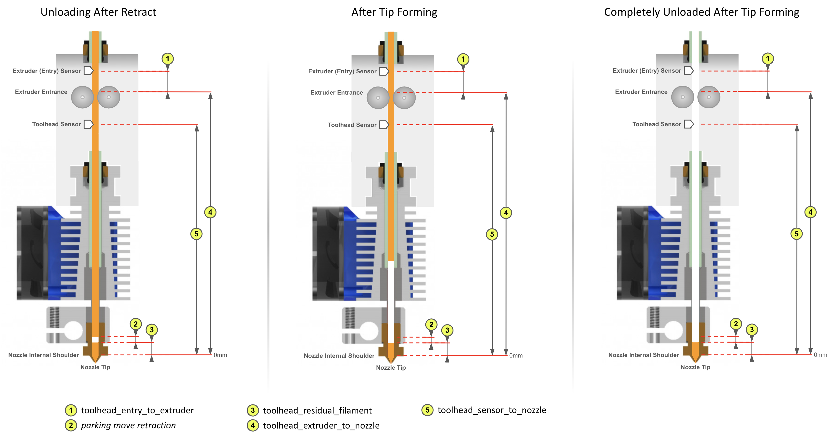
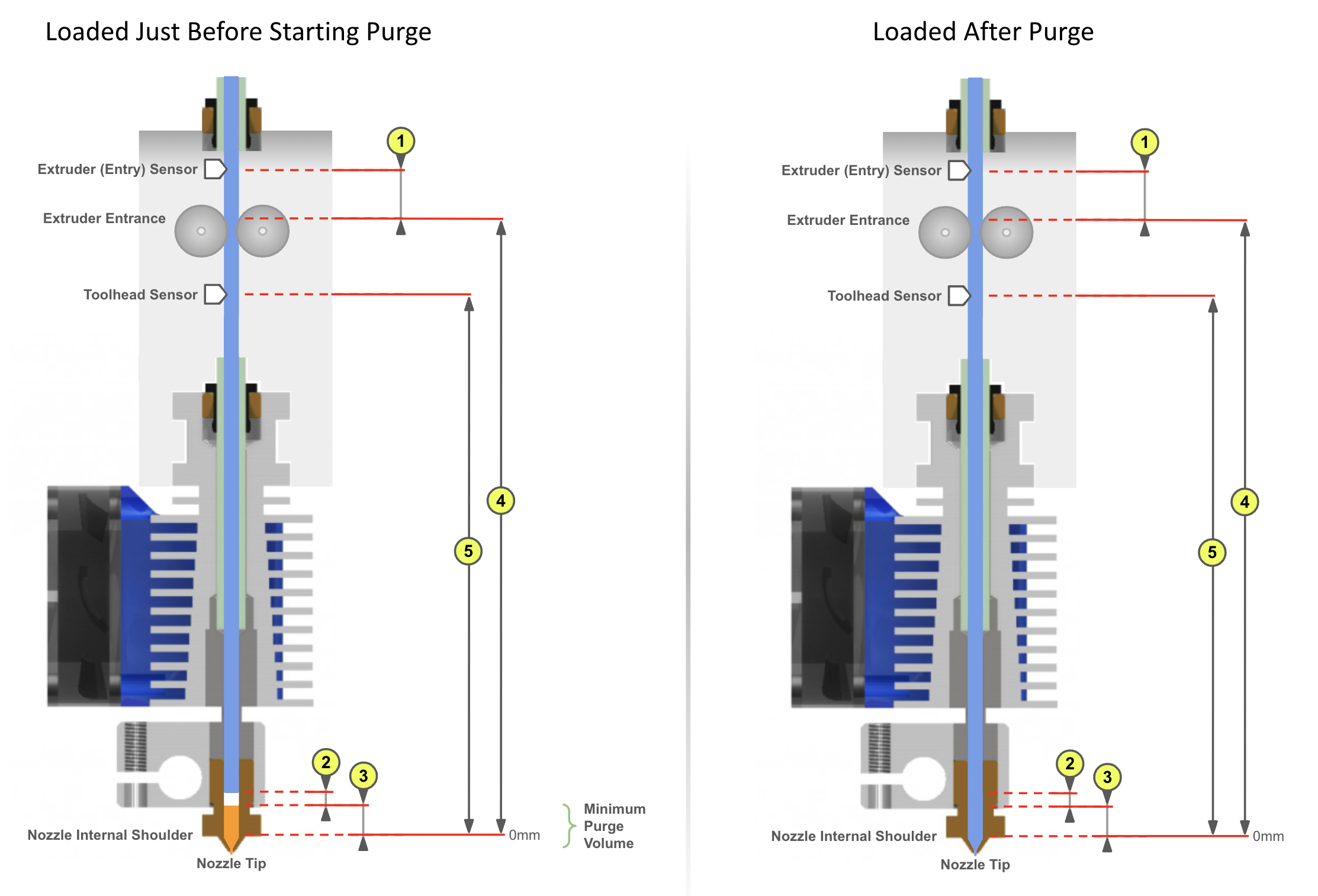
So toolhead_extruder_to_nozzle/toolhead_sensor_to_nozzle are treated as
theoretical, CAD-derived values, and toolhead_residual_filament separately
represents how much to shorten the load move by so new filament butts up
against the old without blobbing. In practice, determining these has mostly
been trial and error - including which of toolhead_residual_filament or
toolhead_sensor_to_nozzle to adjust when something's off.
Walking through a toolchange (orange to blue filament) makes the relationship between these concrete:
With Tip Forming
With Toolhead Tip Cutting
Tip cutting is a little more involved, and introduces two more macro variables (see Calibrating the Toolhead below):
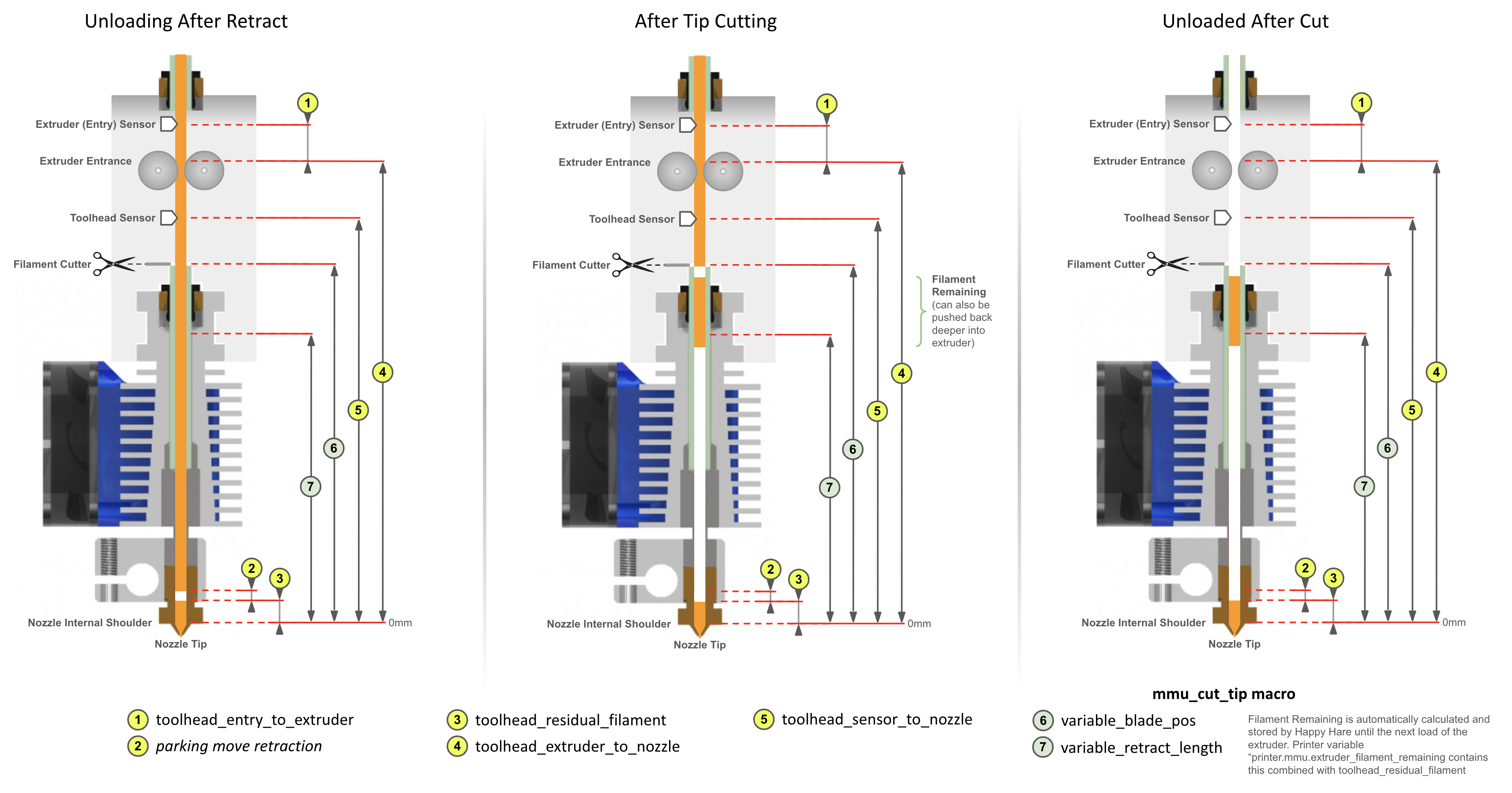
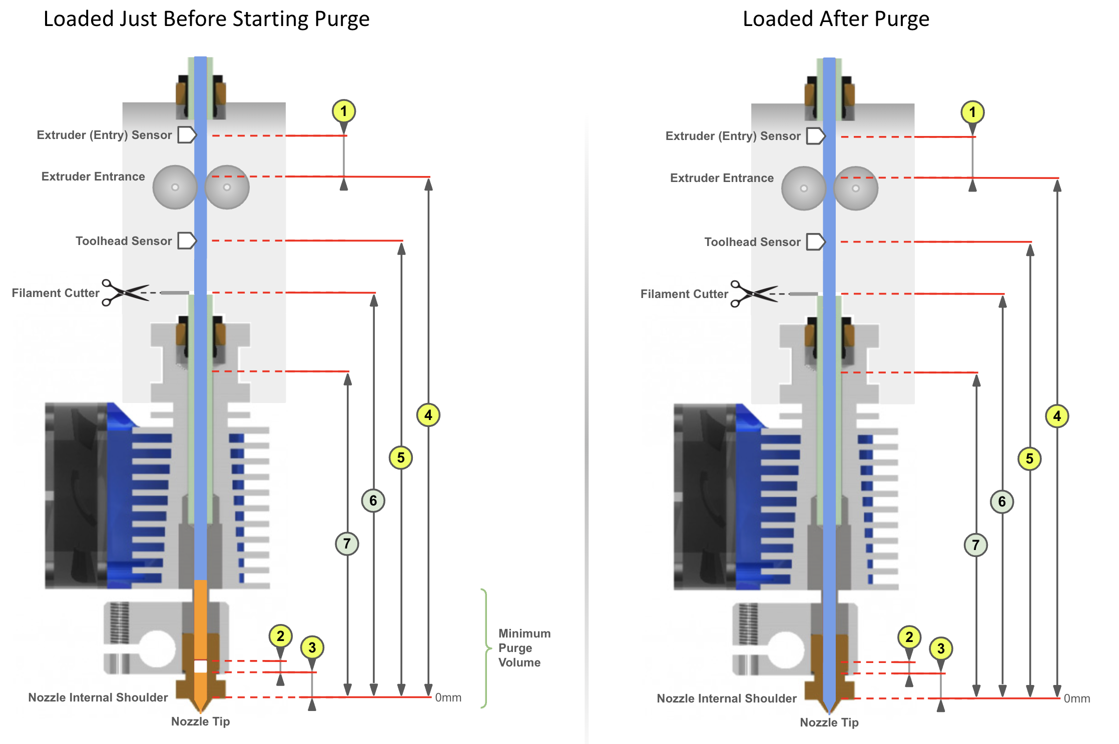
The remaining cut filament fragment and the residual filament are both accounted for automatically, as long as the parameters are configured to match this illustration.
Tip
printer.mmu.extruder_filament_remaining reports the total filament
left in the extruder - toolhead_residual_filament plus any cut tip
fragment. printer.mmu.toolchange_purge_volume combines that with the
slicer's own purge-volume matrix to give the total suggested purge
volume for the current toolchange.
Important
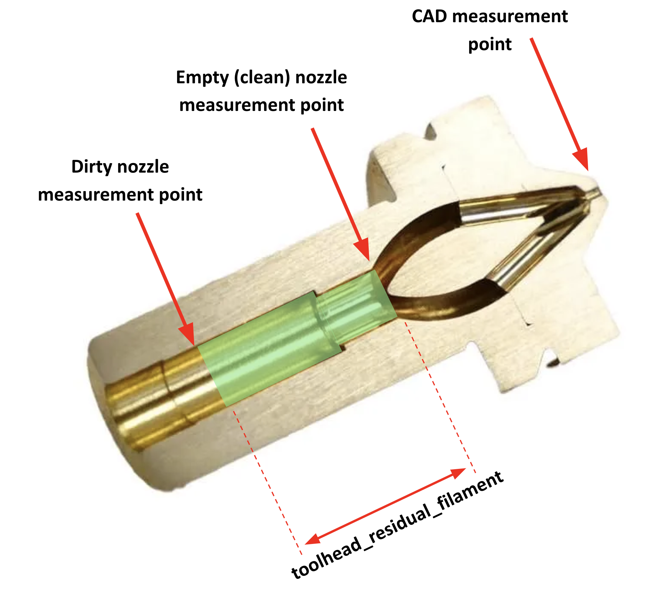
- The nozzle's internal "shoulder" is the real 0mm reference point for most of these settings - on a CHT nozzle, further from the tip than on a regular one.
toolhead_*_to_nozzleandtoolhead_residual_filamentare related - tuning one while ignoring the other works, but getting both right is what lets Happy Hare actually control load/unload movement and purge volume accurately.toolhead_residual_filamentdepends heavily on your extruder and nozzle - high-flow and CHT setups generally need a noticeably larger value than regular ones.
Calibrating the Toolhead
Every one of the CAD-derived settings above except toolhead_residual_filament
can, in principle, be measured directly from a CAD model (using the internal
nozzle shoulder as the reference point - awkward on a CHT nozzle, see the
cutaway below). With a toolhead sensor fitted, there's a faster, automated
way: MMU_CALIBRATE_TOOLHEAD.
Step 1: Cold pull to empty the nozzle
Calibration needs to start from a genuinely clean, empty nozzle - see
Feature: Cold Pull, including the guided
MMU_COLD_PULL macro.
Step 2: Calibrate the empty toolhead dimensions
Reattach the bowden tube if you removed it for the cold pull, select the gate you want to calibrate with, and make sure filament is available and parked at the gate - not loaded into the extruder yet. Then:
MMU_CALIBRATE_TOOLHEAD CLEAN=1
(add SAVE=0 to measure without persisting, e.g. to double-check
repeatability). This runs a series of probing moves on a cold extruder and
reports the empty-toolhead dimensions:
Measuring clean toolhead dimensions after cold pull...
Measured toolhead_sensor_to_nozzle: 62.1
Measured toolhead_extruder_to_nozzle: 70.6
Measured toolhead_entry_to_extruder: 7.9
-----------------------------------
Calibration Results (clean nozzle):
> toolhead_extruder_to_nozzle: 70.6 (currently: 70.0)
> toolhead_sensor_to_nozzle: 62.1 (currently: 62.0)
> toolhead_entry_to_extruder: 7.9 (currently: 8.5)
-----------------------------------
New toolhead calibration active until restart. Update mmu.cfg to persist settings
The results apply immediately but only persist across a restart once
you've copied them into mmu.cfg yourself, once the whole calibration
below is finished.
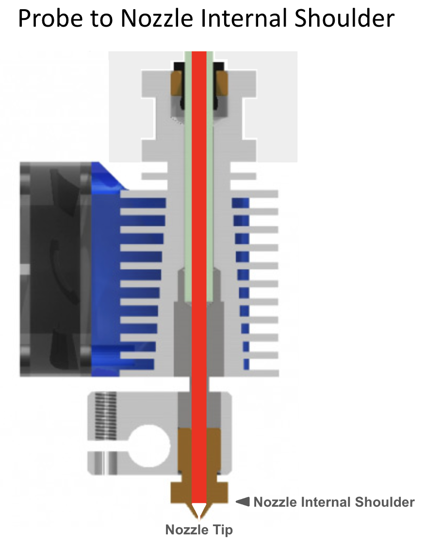
Because the extruder started empty, this step establishes the internal
nozzle shoulder's position and, from it, toolhead_extruder_to_nozzle,
toolhead_sensor_to_nozzle, and toolhead_entry_to_extruder all at once.
Tip
- Re-run with
SAVE=0any time you want to sanity-check repeatability without touching your saved config - just remember the filament will grind a little in the gears/extruder each time, so eject, cut off the used portion, and use a fresh segment for the next attempt. - If you have a filament tension/compression sensor (e.g. Belay) on the bowden path, lock it in its fully-extended position (or remove it and fit a coupler) before calibrating - the filament path length needs to stay static throughout.
Step 3: Load and dirty the nozzle
Simulates the filament normally left molten in the nozzle after an eject. Start with a fresh piece of filament (the previous step likely ground the last one slightly):
Using tip forming:
MMU_LOAD(orTx)- Manually extrude a little filament from the web UI
MMU_UNLOAD- Turn the nozzle heater off (target 0°C)
Using tip cutting, avoid the actual cutting step so the toolhead is left dirty the same way an eject normally would:
MMU_LOAD(orTx)- Manually extrude a little filament from the web UI
MMU_UNLOAD SKIP_TIP=1- Turn the nozzle heater off (target 0°C)
Step 4: Calibrate residual filament
With the nozzle now "dirty," measure how much filament that leaves behind:
MMU_CALIBRATE_TOOLHEAD DIRTY=1
-----------------------------------
Calibration Results (dirty nozzle):
> toolhead_residual_filament: 3.0 (currently: 3.4)
-----------------------------------
New calibrated ooze reduction active until restart. Update mmu.cfg to persist
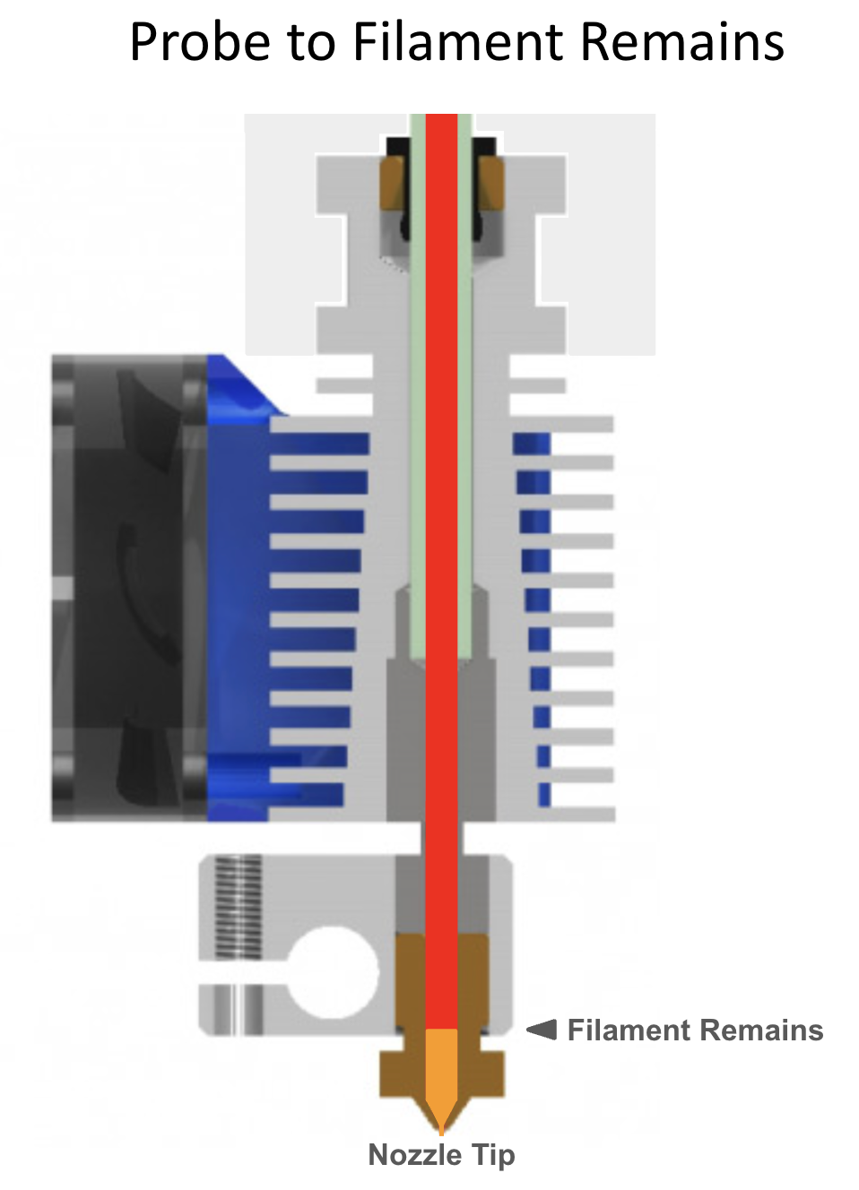
The difference between this reading and Step 2's clean one is exactly what
toolhead_residual_filament compensates for. This step also re-measures
toolhead_entry_to_extruder - it should land within about 1mm of Step 2's
value; a bigger gap usually means one of the two measurements wasn't
accurate and is worth re-running.
Tip
- Re-run this as often as you like - different filament, a tip-forming macro change, and so on can all shift the result. Fresh filament segment each time, same reasoning as Step 2.
SAVE=0also works here as a quick way to measure how much filament a cut tip left behind, without polluting your realtoolhead_residual_filamentvalue with it.- No filament cutter? Calibration is done - copy these results and
Step 2's into
mmu.cfg. With a cutter, continue to Step 5. - Lock any bowden tension/compression sensor in place here too, same as Step 2.
Important
Treat the calibrated toolhead_residual_filament as a starting point,
not a final answer - fine-tune it against a real print with
toolhead_ooze_reduction, a small adjustment layered on top (see
Feature: Tip Forming and Purging
for what to look for). This should be the very last, smallest tweak -
not a substitute for getting the dimensions above right first.
Step 5: Calibrate the tip-cutting blade position (if fitted)
Toolhead dimensions having changed likely means the cutter's own blade
position needs recalibrating too - variable_blade_pos and
variable_retract_length (both in mmu_macro_vars.cfg) control how much
cut filament is left behind, and need to be correct to avoid oozing on the
next load.
MMU_LOAD(orTx) to load filament.- Turn the nozzle heater off and let it cool.
- Manually actuate the cutter a couple of times to get a clean cut.
MMU_UNLOAD SKIP_TIP=1- unload without re-running tip forming.-
With filament unloaded/parked and the nozzle cold:
MMU_CALIBRATE_TOOLHEAD CUT=1----------------------------------- Calibration Results (cut tip): > variable_blade_pos: 36.2 (currently: 37.5) > variable_retract_length: 5.0-36.2, recommend: 32.2 (currently: 32.5) ----------------------------------- New calibrated variables active until restart. Update mmu_macro_vars.cfg to persist
Tip
Rather than load/cut/cool, you can instead leave the extruder unloaded and simply press and hold the cutter blade closed for the whole measurement - add 0.5mm to the reported distance to account for the blade's own thickness.
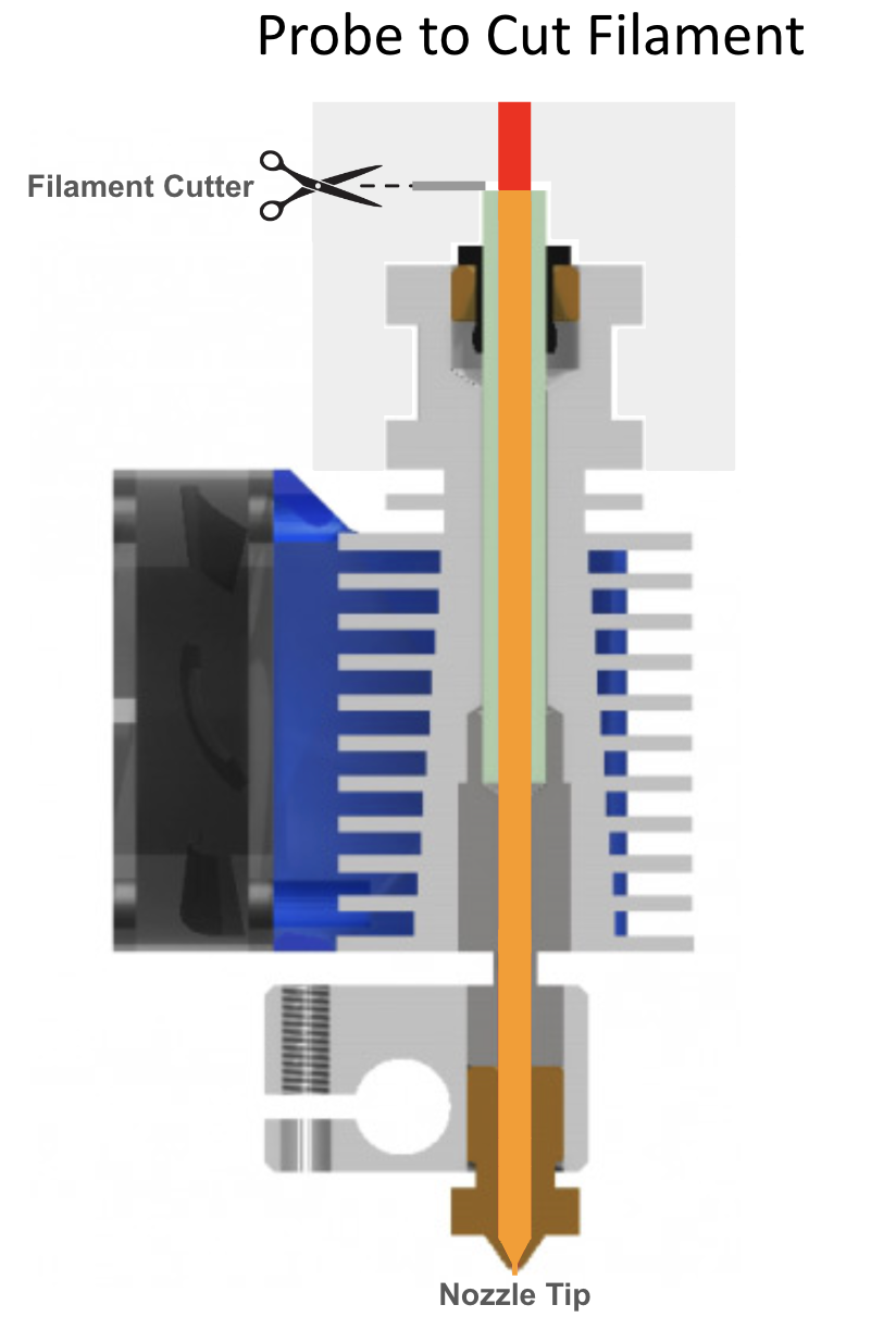
A larger variable_retract_length needs less purge to clear the previous
color, but too aggressive risks clogs (you're cutting a still-hot section
of filament) - roughly 5mm shorter than variable_blade_pos is a reasonable
starting point; shorten it further if clogging shows up. Lock any bowden
tension sensor in place for this step too.
Summary of MMU_CALIBRATE_TOOLHEAD options
| Order | Option | Measures |
|---|---|---|
| 1 | CLEAN=1 |
toolhead_extruder_to_nozzle, toolhead_sensor_to_nozzle, toolhead_entry_to_extruder - run on a clean extruder, right after a cold pull |
| 2 | DIRTY=1 |
toolhead_residual_filament - run on a dirty extruder with a formed (not cut) tip |
| 3 | CUT=1 |
variable_blade_pos (and suggests variable_retract_length) - run after loading, manually cutting, and MMU_UNLOAD SKIP_TIP=1 |
UNIT= (name or number) targets a specific unit on a multi-unit machine,
optional if you only have one.
Toolchange Retraction and Z-Hop
Just as during printing, the extruder needs its pressure relaxed before a travel move, or it oozes. Every parking move (see Toolchange Movement for the full mechanism) bundles this as one of five values in its per-operation tuple - x, y, z-hop, z-hop ramp, and retraction - rather than as separate settings:
variable_park_toolchange: -999, -999, 1, 10, 2
is a 1mm z-hop (with a 10mm horizontal ramp) and 2mm of retraction, applied immediately before the toolhead moves away. 2-3mm of retraction is usually enough to minimize oozing (a little more on high-flow systems); the retract/un-retract speed itself is set separately and independently of your normal load/unload speeds:
variable_retract_speed: 25      ; mm/s
variable_unretract_speed: 25    ; mm/s
Un-retraction happens at the end of the toolchange, right after the z-hop reverses, correctly re-pressurizing the extruder - so it's never fully pressurized during the travel move itself, which is most of what keeps oozing down.
The z-hop itself exists so the hot nozzle doesn't rest on the print (or mark it) while parked, but a straight vertical retract-and-lift still tends to string on many filaments - pulling viscous filament straight up out of the nozzle. The z-hop ramp - a horizontal component to the same move - breaks that up into a faster, longer travel move than a pure vertical lift would allow, angled toward the build plate's centre so it can't run off the edge.
See Toolchange Movement for the complete parking mechanism this all belongs to - which operations park in which context, the other hook positions, and how the toolhead returns to the print afterward.
Summary of Tuning Steps
In order:
MMU_CALIBRATE_TOOLHEADresults, persisted inmmu.cfg.toolhead_ooze_reduction, also inmmu.cfg- the small manual fine-tune on top.- Parking tuples (retraction, z-hop, z-hop ramp together) in the
MOVEMENTsection ofmmu_macro_vars.cfg.
graph LR
    A[MMU_CALIBRATE_TOOLHEAD
CLEAN / DIRTY / CUT] --> B[toolhead_ooze_reduction]
    B --> C[Parking tuple per operation:
retraction + z-hop + z-hop ramp]
Cleaning the Extruder with a Cold Pull
A cold pull is a generally useful maintenance trick - clearing carbon
deposits that build up over time and cause under-extrusion or dark spots -
as well as the way to get a genuinely clean nozzle before the calibration
above. See Feature: Cold Pull for the full manual
and MMU_COLD_PULL-guided procedures, parameters, and per-material
temperature defaults.
See also
- Feature: Cold Pull - cleaning/prepping the nozzle before calibration
- Command Reference:
MMU_CALIBRATE_TOOLHEAD - Command Reference:
MMU_UNLOAD - Toolchange Movement
- Feature: Tip Forming and Purging
- Printer Variables